An A-SID trip, part 2
Posted by Stefano on Fri, 08 Jul 2022 15:45:08 GMT.

Getting the design to actually work was easier said than done, to put it mildly. This second part of the story is about the implementation details.
Assemblying the program
Let's start from the end.
The C64 version of A-SID is made of two parts:
- a boot program written in BASIC which:
- implements autorun by overriding the BASIC idle loop address stored at memory locations $0302-$0303 (this works when running the final .prg file on VICE, but it isn't enough to autorun from actual tape — I only found out potential solutions while writing this post);
- discourages users with photosensitive conditions from using the program;
- allows the user to connect and calibrate an expression pedal.
- the main program coded in 6502/6510 assembly.
The boot program
The former part was literally an afterthought, and it probably shows. However, there are some interesting bits related to the calibration procedure:
- the paddle value is actually read by a routine implemented in the main program, which is an adapted version of a piece of code found in the Commodore 64 Programmer's Reference Guide (this one) — essentially, it is the SID chip that actually reads paddles and the values are then accessible at memory locations $D419 and $D41A, yet extra steps need to be taken to make the reading reliable, such as disabling interrupts and some waiting, which I'm not sure can be effectively implemented in BASIC alone;
- as already anticipated in the previous post, the user is asked to first set the expression pedal to minimum, corresponding to low resistance, which allows the program to autodetect if there is an expression pedal connected at all and decide whether to continue with the calibration or rather jump straight to the main program;
- the program uses minimum, middle, and maximum paddle values to build a lookup table that maps expression pedal positions to cutoff modulation values in the range [-127, 127] — since the CPU lacks hardware multiplication and division which would be normally needed to compute modulation values, here we're using the slow BASIC routines at boot to precalculate all possible such values and avoid these operations in the main program.
I used a program called bas2prg from prg-tools to convert the BASIC source code to binary data suitable to create the final .prg file. I knew petcat from VICE existed, but I couldn't get it do what I wanted quickly and couldn't be bothered learning it when I had an already working alternative at hand.
The main program
The main program was coded directly in 6502/6510 assembly to obtain the best possible performance. I've used the excellent ACME Cross-Assembler to build the program — it is a rare case of software that does what it's supposed to do, doesn't get in the way, is intuitive to use, and properly documented.
At the beginning of the source code you'll find the memory map of the program itself, which is necessary to keep track of all variables and data.
First, the program initializes the VIC-II chip, switching to Standard Bitamp Mode, the SID chip, and sets initial values.
Then the main loop begins. This is itself composed of two parts:
- the first part reads the joystick and expression pedal and eventually updates the variables that represent the current (focused) parameter index and its value, as well as the mapped cutoff modulation value due to the expression pedal;
- a second part that implmenets the LFO, computes the modulated cutoff, and updates the GUI and the SID registers.
The second part is executed more frequently than the first (4:1 ratio) to keep both the GUI reactive and LFO-induced cutoff modulation smooth, as well as to limit the joystick "sensitivity". In the case of left/right joystick movements, which change the focused parameter, I have added extra counters to limit sensitivity further (the joystick needs to read left/right 3 times in a row to actually cause a change). Perhaps this approach is suboptimal and I could have used interrupts instead, or maybe not. TBH, I haven't even reasearched this, as in practice it worked well enough so I didn't care.
LFO
The SID chip has no LFO, hence I implemented one in software. It has sinusoidal output in [-127, 127] (integer of course) and two parameters, namely amount (that is, output scaling) and speed. The implementation consists of a pretty straightforward phase generator + waveshaper structure, with a couple of tricks to make it cheap to compute on the C64.
The phase generator just regularly updates a variable that represents the current phase of the LFO according to the speed setting. In other words, this variable is incremented each time by a given amount (that depends on speed) and when "the cycle finishes", the value is brought back into the valid range by division remainder. Simply choosing the phase to be represented by an 8-bit unsigned number, there's no need to perform division remainder as naturally-occurring integer addition overflow effectively does the phase wrapping for us.
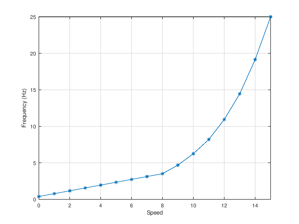
As every joystick-controlled parameter in A-SID can assume 16 possible values, there are ineed 16 possible phase increments for the LFO speed. Once again, to avoid computations, I used a small lookup table that maps numbers 0-15 to phase increments. Given how the code is structured, the actual LFO frequency depends on the amount and type of instructions in the main loop and the whole operation is also affected by phase noise/jitter etc. Long story short, I decided on the actual values when the rest of the program was completed, so that no further changes needed to be done. Also, I wanted LFO frequency to be mapped logarithmically (in the sense of logarithmically spaced, that means exponentially varying in value when considering linear intervals) w.r.t. the LFO speed parameter: first I found out the phase increment range that I liked (1 and 64 mapped to about 0.4 and 25 Hz, respectively, which is good), and then I used GNU Octave's logspace function and applied rounding. As the smaller values would be rounded towards the same numbers, I replaced the lower part of the mapping with a linear map, thus finally getting this mapping.

Then again, to spare precious CPU cycles and avoid computations, I merged the sinusoidal waveshaping (that is the conversion of the phase signal to the actual output sinusoid, usually done through a matheatical function) and output scaling into a single operation implemented by a single multi-dimensional lookup table with 16x256 elements (as we have 16 LFO amount parameter values and 256 phase values). A GNU Octave script generates the data, of which here is a graphical representation.

Cutoff modulation and mapping
Cutoff is internally stored in an unsigned 8-bit variable, hence it can assume 256 values. It is computed like this:
- the joystick-controlled cutoff parameter is multiplied by 16, and then 8 is added to the result (the code actually uses using cheap bitwise operations as these numbers are powers or 2) — this is because, like the other parameters, we have 16 possible values, hence the multiplication allows us to cover the whole avaliable range and the addition puts us in the middle of each "subrange";
- the mapped paddle (expression pedal) value (remember, in [-127, 127]) is added with necessary clipping to avoid overflow;
- likewise, the same happens with the LFO value.
In other words, LFO and expression pedal add bipolar modulation to the bare cutoff and the result is a number in [0, 255].
This resulting number needs to be further mapped into an 11-bit value that the SID chip uses to represent cutoff. After some measurements on the chip (which I will detail in a future post in this series) I found out that the 8580 maps these values linearly w.r.t. actual filter cutoff frequencies, hence once again a lookup table was needed to obtain a nice logarithmic mapping in the range of interest. Here's a graphical representation of such mapping.

GUI
The VIC-II chip in Standard Bitmap Mode draws the screen using two chunks of memory, one containing the so-called bitmap, which stores information on whether each pixel has to be painted with foreground or background color, and the colormap, which specifies what are the foreground and background color for each 8x8 tile.
The GUI is mostly based on a single image colored in 4 different ways, according to the current modulated cutoff value. The quickest way I could think of to actually change color to large portions of the screen was then to use a single bitmap and 4 different colormaps to switch on the fly, and I have to say it works beautifully (but it requires quite some RAM, which luckily I had available). Here is a graphical representation of the bitmap and one of the colormaps.


For such a scheme to work, colormaps/bitmaps need to match exactly. Plus, the sliders and labels needed to be colored at runtime, since the focused parameter can change, which means having the program also edit the colormaps while running. Similarly, hiding/showing parts of the sliders was also implemented by editing the colormap (I just used white as both background and foreground to hide parts). Such operations could be implemented efficiently as long as foreground/background color choice was consistent across sliders and labels.
I could have probably drawn and generated the graphics data easily using a tool like Pixcen, but I was having problems with it that I later discovered were completely my fault, but in the meanwhile I decided I'd just create myself a tool that converted images to C64 bitmaps and colormaps and that allowed to exchange foreground and background color in each tile. This was quick to do using browser technology. If you're interested you can find it here.
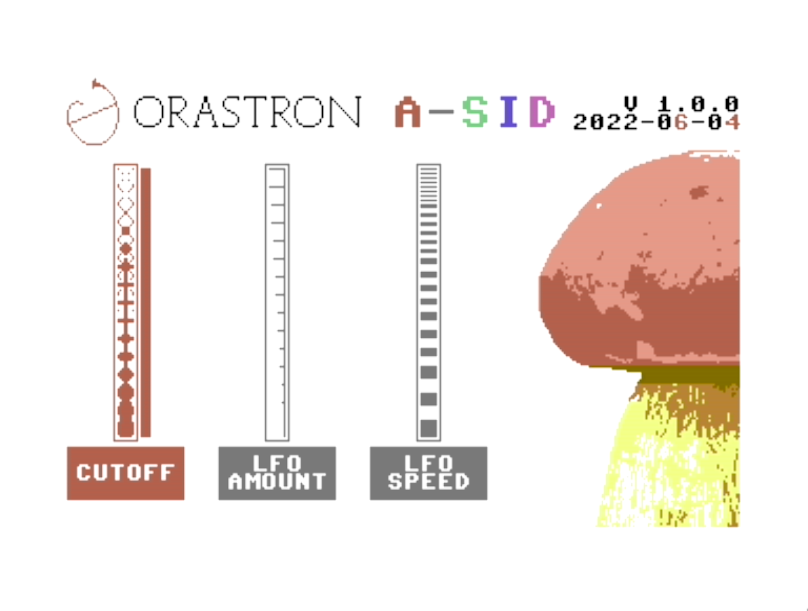
Finally, as you can guess from the screenshot image below, the bar indicating the current modulated cutoff value needed to be drawn by also modifying the bitmap. In order to obtain pixel-level resolution, a somewhat sophisticated algorithm was needed, but I won't go into details. If you really want to know more, you can take a look the source code.

Conclusions
It took me a few weeks to get all of this into its final shape. It's been somewhat hard at times (I've never done any 6502/6510 assembly programming before) but also very rewarding. The time available was limited, so I had to take some risks here and there, but it worked out great in the end.
Technically speaking, the code uses quite some RAM but is incredibly fast for a 1 MHz 8-bit machine. No multiplications or divisions are involved after the boot phase. Despite the limited amount of time I had to code, I don't think I could have easily done better performance-wise, which was my main concern from the start.